PWM Motor Controller & H-Bridge Assembly
A custom-built motor driver demonstrating PWM speed control and bidirectional motor operation.
Tools/Technologies: Atmega328P (Arduino), Assembly (Microchip Studio), Custom H-Bridge, Breadboarding/Soldering, 3D Printing, Fusion 360, Magnetic Power Transfer Date: Spring 2024
Overview
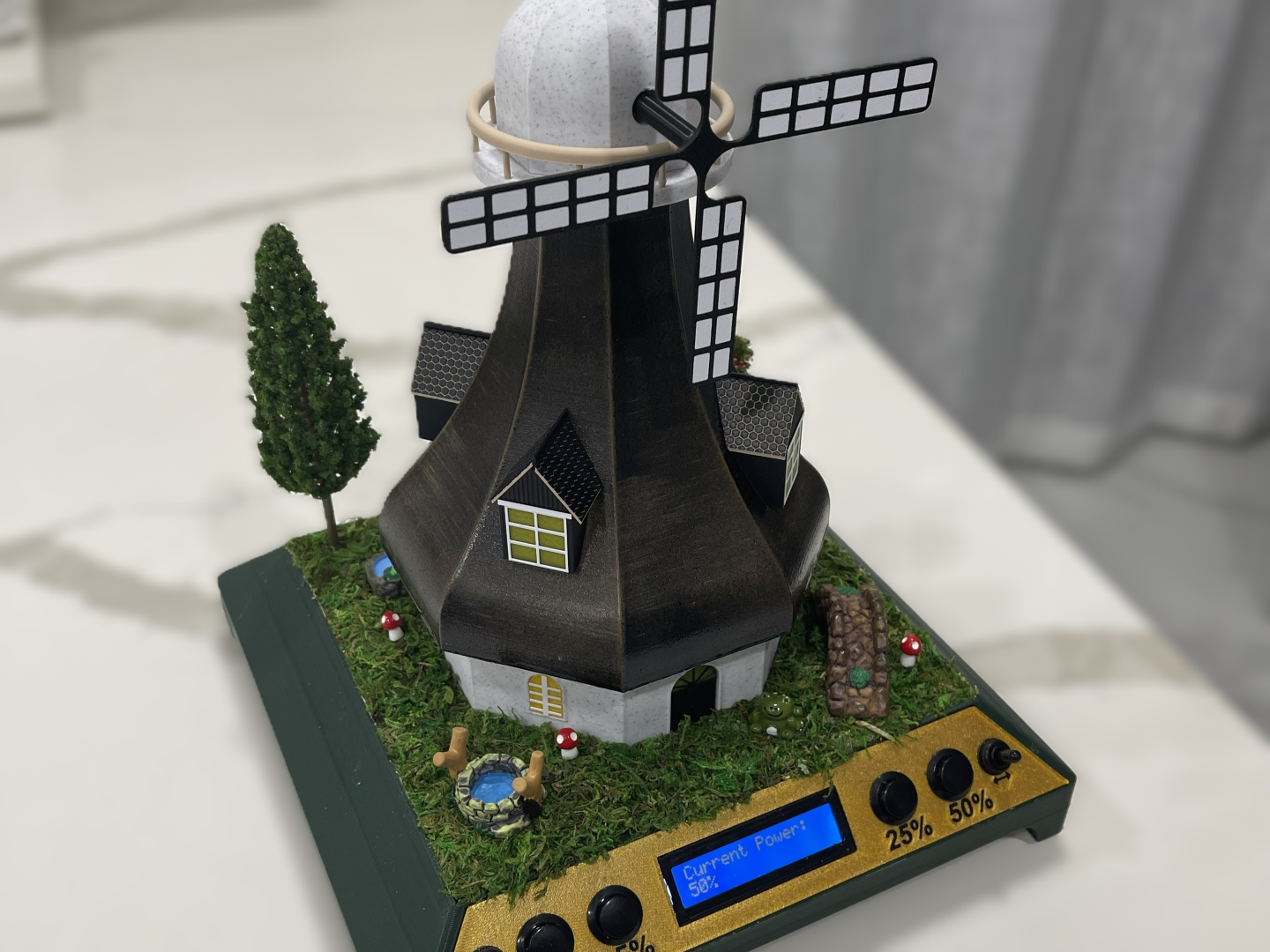
This project demonstrates how to control DC motor speed using pulse-width modulation (PWM) and how to reverse motor direction using a discrete H-bridge circuit. The system uses an Atmega328P programmed in assembly to generate precise timing signals for the driver. Our team integrated the electronics into a 3D-printed windmill enclosure to gain mechanical design experience while creating an engaging, visible demonstration. Neodymium magnets were used to route power cleanly into the assembly while keeping the internal components easily accessible for educational purposes.
My Role
- Designed and assembled the discrete H-bridge circuit using reference schematics (no off-the-shelf driver ICs).
- Led the electrical integration, including wiring, power routing, and component layout.
- Modeled and 3D-printed the windmill housing in Fusion 360, focusing on fit, accessibility, and presentation.
- Contributed to the microcontroller firmware (assembly), primarily reviewing logic and assisting with PWM/direction test routines.
- Integrated neodymium magnet contacts to provide power while keeping the electronics fully accessible.
Technical Challenges
- Ensuring transistor switching reliability: Required careful selection and orientation of discrete components to avoid thermal overstress and switching overlap.
- Minimizing shoot-through in the H-bridge: Electrical layout and firmware timing both had to be coordinated to prevent simultaneous high-side/low-side conduction.
- Power transfer through magnets: Conductivity had to remain stable despite motor movement and allow for reliable mounting/dis-mounting of motor tower during presentations.
- Mechanical packaging constraints: The windmill design needed to house the circuitry cleanly while exposing key electronics for demonstration and grading.
Key Design Decisions
- Discrete H-bridge instead of a driver IC: Enabled deeper understanding of switching behavior and allowed full customization of the current path.
- Magnetic power contacts: Chosen to eliminate bulky wiring and maintain accessibility of internal circuits.
- Accessible 3D-printed enclosure: Prioritized ease of assembly, part alignment, and safe presentation of exposed electronics.
Results / Outcomes
- Achieved smooth PWM-based speed control with clean bidirectional operation.
- Verified stable power delivery through the magnet contacts during continuous operation.
- The enclosure served as an effective instructional model, clearly displaying electronics while providing mechanical stability.
- Strengthened teamwork across electrical design, firmware development, and CAD/mechanical integration.